Automotive benchmarking company Munro & Associates has been tearing into a Tesla Model Y for a number of weeks now, and perhaps the company’s most intriguing discovery is the amazing cooling system consisting of an “Octovalve” hooked to a fascinating coolant manifold that interfaces with a ridiculously complex refrigerant manifold. Just look at this thing and try to wrap your head around it.
Before we get into this, I have to admit that this article isn’t going to be a typical, overly-technical DT-deep dive. Munro & Associates sells insight, so it’s not going to give away all the secrets it discovers without charging a few doubloons. Still, the video below does provide fascinating visuals of Tesla’s cooling system—visuals never seen before by the public. Have a look:
Let’s take a little step back.
The big players in the Tesla Model Y’s cooling system are located in one small area at the front of the car, just between the frunk and the body’s front bulkhead. Munro’s president Cory Steuben called the packaging “second to none,” telling me: “This whole heat pump is packaged in the space of a suitcase and it’s incredible.” Take a look:
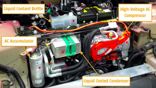
What you see there is a high-voltage AC compressor on the right, with lines that feed into an aluminum refrigerant manifold (which has components like an accumulator and condenser hooked to its front). On the back side of the refrigerant manifold is a coolant manifold, which you can’t see in the image above, though the coolant bottle is shown sticking out just behind the strut brace. For reference, I took this photo from underneath the Model Y; it shows the coolant manifold just above the front passenger’s side CV axle:

Let’s take a closer look at the whole setup, beginning with the refrigerant system. The main parts are the accumulator, condenser, chiller, AC compressor, and electric thermal expansion valves.
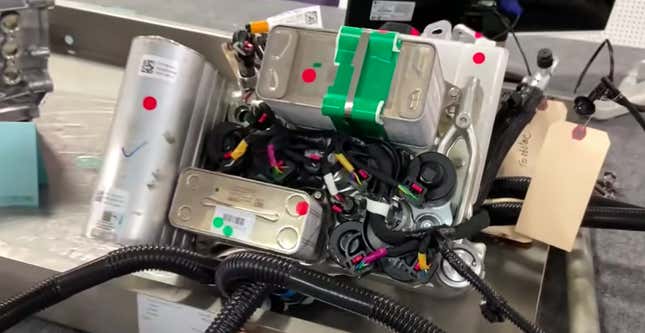
The accumulator is the thing you see on the left there, and Sandy Munro in his video makes mention of its nice friction stir-welded construction. It likely contains a hygroscopic desiccant meant to remove moisture from the AC system, it also probably contains some sort of filter to remove contaminants, and it may also act to prevent liquid ingestion into the compressor (you want the refrigerant to be a gas before the compressor tries to squeeze it).
Also part of that refrigerant manifold subsystem is a liquid cooled condenser, an LCC.
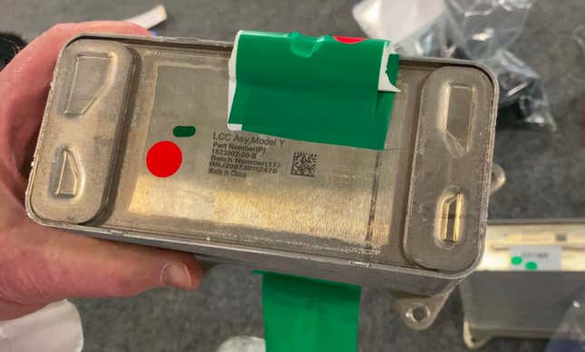
Most modern cars have an air-to-refrigerant condenser that sits near the front of the cooling module, almost always ahead of the radiator. The condenser’s job is to cool refrigerant so that it can be used to chill various components—generally a vehicle’s cabin by sending the frigid refrigerant to an another heat exchanger in the dash (the evaporator) to pick up heat from air in the car’s interior. AC service company Ariazone’s Air Conditioning Training Manual describes this a bit:
Refrigerant entering the condenser will be a high-pressure high temperature vapor. As the refrigerant vapor travels through the tubes of the condenser, heat is given off to the cooler ambient air; the refrigerant vapor condenses and changes to a liquid state.
In the case of the Tesla Model Y, instead of having an air-to-refrigerant heat exchanger (condenser) at the front of the car, there’s instead an air-to-glycol-based-coolant low-temperature radiator out front. That radiator sends cold coolant to the “stack”-style condenser you see here, which chills the gaseous refrigerant to bring it to a liquid state.
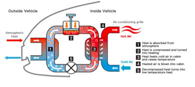
But this condenser isn’t just used to replicate what a typical car’s condenser does in an AC system. It also acts as a key part of a heat pump, which is a way to heat the cabin efficiently without relying entirely upon an electric heating element (Fun fact: Per Steuben, there are three condensers and three thermal expansion valves—more on those in a bit—in the HVAC unit itself). A heat pump can be thought of as an AC system in reverse—strategically using the compressor and an expansion valve to heat refrigerant, and using that heated refrigerant to warm the cabin or possibly other components. I won’t pretend to understand how Tesla’s system works, and Elon Musk himself said the “Third Row Tesla” podcast that “It’s kinda like an air conditioner backwards. There’s no easy way to describe a heat pump. Just look at the Wikipedia article.”
The main point, though, is that Tesla has all of this stuff tightly integrated into a small package, and controlled with complex valving.
On a typical automobile, after the condenser, the high-pressure liquid refrigerant tends to enter a Thermal Expansion Valve, which is used to drop the pressure in the system. In some ways, such a valve can be thought of as a variable orifice or a metering valve, carefully controlling how much refrigerant flows into the evaporator. Such expansion “metering” valves are the black pancake-looking plastic things that you see plugged into the aluminum manifold, attached to some connectors:
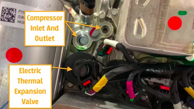
The photo above also shows where the AC compressor inlet and outlet hoses hook to the manifold.
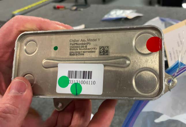
The second, smaller “stack” or “plate” heat exchanger hooked to the refrigerant manifold is the chiller. Its job is to act as another interface between the liquid coolant and the refrigerant. Acting similarly to an evaporator in a typical AC system, the chiller’s main purpose is to allow the refrigerant to pick up heat from another fluid, in this case, liquid coolant that flows through the battery pack, power electronics, and other components to keep them cool. The chiller’s role is especially critical when ambient temperatures are high.
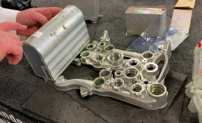
The semi-solid forged aluminum refrigerant manifold is a fascinating contraption. With the help of the various thermal expansion valves, it apportions refrigerant between the different heat exchangers and other components in the AC system.
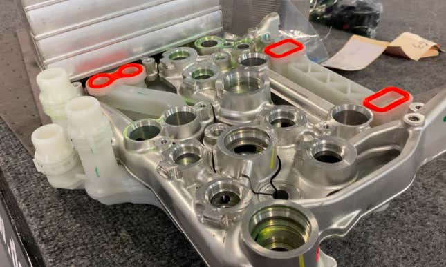
It is a truly beautiful bit of machining. You can see thin cut-out channels between the ports. Those were, per Munro, done by an electric discharge machine, and they exist to allow for thermal expansion of the aluminum without failure.
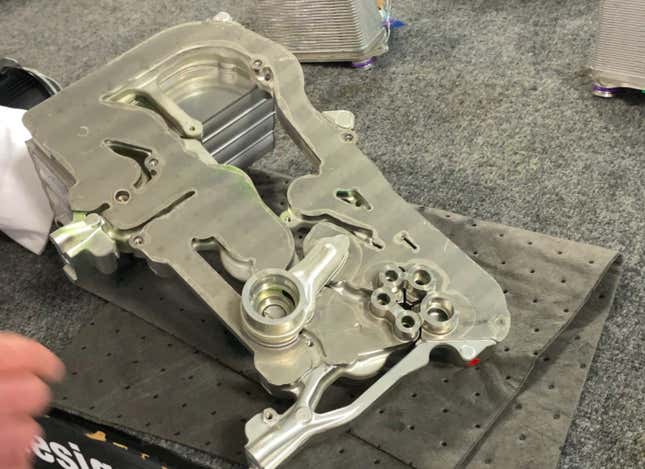
The back side, you’ll notice, is flat. There’s normally a plate on this surface, where the refrigerant manifold mates with the flat surface of the nylon coolant manifold, as you can see in the photo before the one just above. Here’s a look at the “front” of the coolant manifold—again, the side that mates up with the back side of the refrigerant manifold shown above:
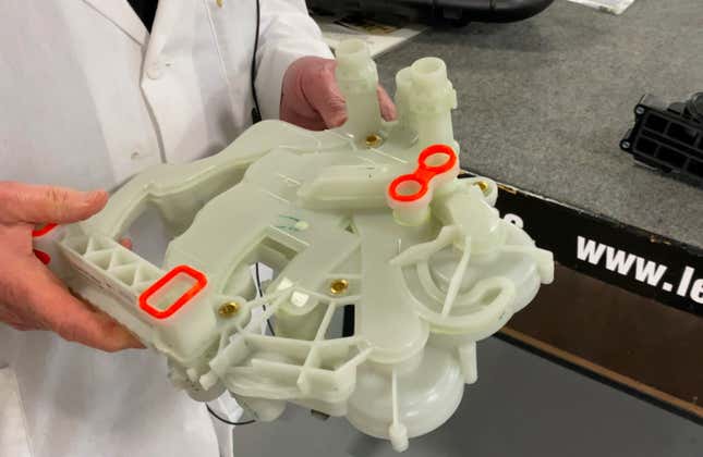
Here’s a look at the back side of the manifold, which is made up of 11 pieces and contains 21 ports:
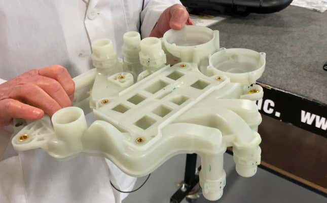
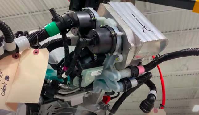
The back side is the more interesting one, because like the front, it contains coolant inlet/outlet ports, but it also has provisions for two electric water pumps and the “Octovalve.” That big rectangular shape molded into the nylon coolant manifold—the one containing the eight rectangular passages—is where the Octovalve sits.
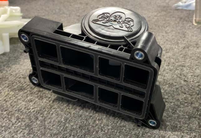
The Octovalve contains a four-position electric stepper motor whose job it is to apportion liquid gycol-based coolant to various components in the car—whether it’s the motors, batteries, power electronics, or other systems that need thermal regulation. Here’s a closer look at the ports/valves and the plastic stepper motor cover (at the bottom):

Right next to the Octovalve are two water pumps that screw into that ornate liquid coolant manifold, and circulate the glycol-based fluid throughout the system:
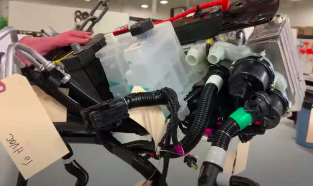
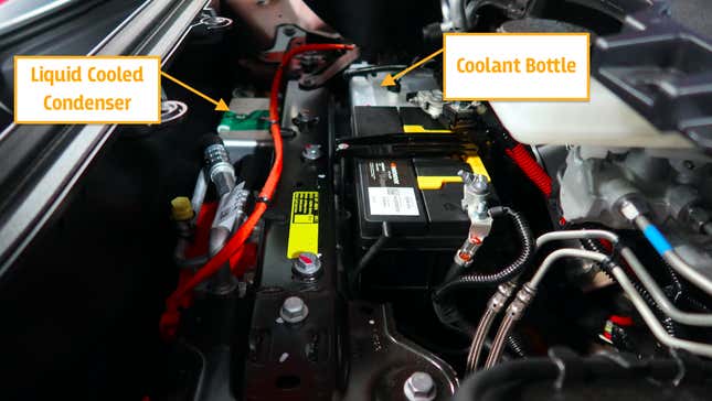
On the opposite side of the Octovalve, and up high, is the coolant bottle (used for filling, and possibly also de-aeration), which is visible under-hood, sitting right next to the 12-volt battery:
You can see it, and the liquid cooled condenser, right here:
There’s obviously quite a complex control system that runs all the thermal expansion valves, that stepper motor in the Octovalve, the compressor, and other parts of this setup. Steuben from Munro told me the valves are hooked to a low-voltage harness, though there doesn’t appear to be a dedicated controller for this system. It’s likely integrated elsewhere.
Tesla discusses, broadly, the role of controllers in its patent, writing:
The control electronics control the components of the vehicle thermal management system to heat the cabin, cool the cabin, heat the battery system, cool the battery system, and cool the drive train. The control electronics may control the compressor to operate in an efficient mode or a lossy mode in which the compressor generates heat. The control electronics may also control the components of the vehicle thermal management system to precondition the battery.
Elon Musk talked about the complexity of this cooling system the “Third Row Tesla” podcast saying:
Applying the concept of a printed circuit board to cooling circuits allows you to achieve a very complex heat exchanger that you literally could not do with tubes.
Indeed, that refrigerant manifold does remind me a bit of a circuit board, and founder of Munro & Associates, Sandy Munro, also seems impressed, comparing it to transmission valve body or a part of a jet engine fuel system:
“This is more like what I would expect to see on a fuel system for jet engines...or a transmission type of a design. These things...are totally different than what we would normally see if we were looking at something designed by a normal OEM.”
I thought the Tesla Model 3's “Superbottle” system was complex, but wow. Just wow.
Updated 3/3/22 with new details.